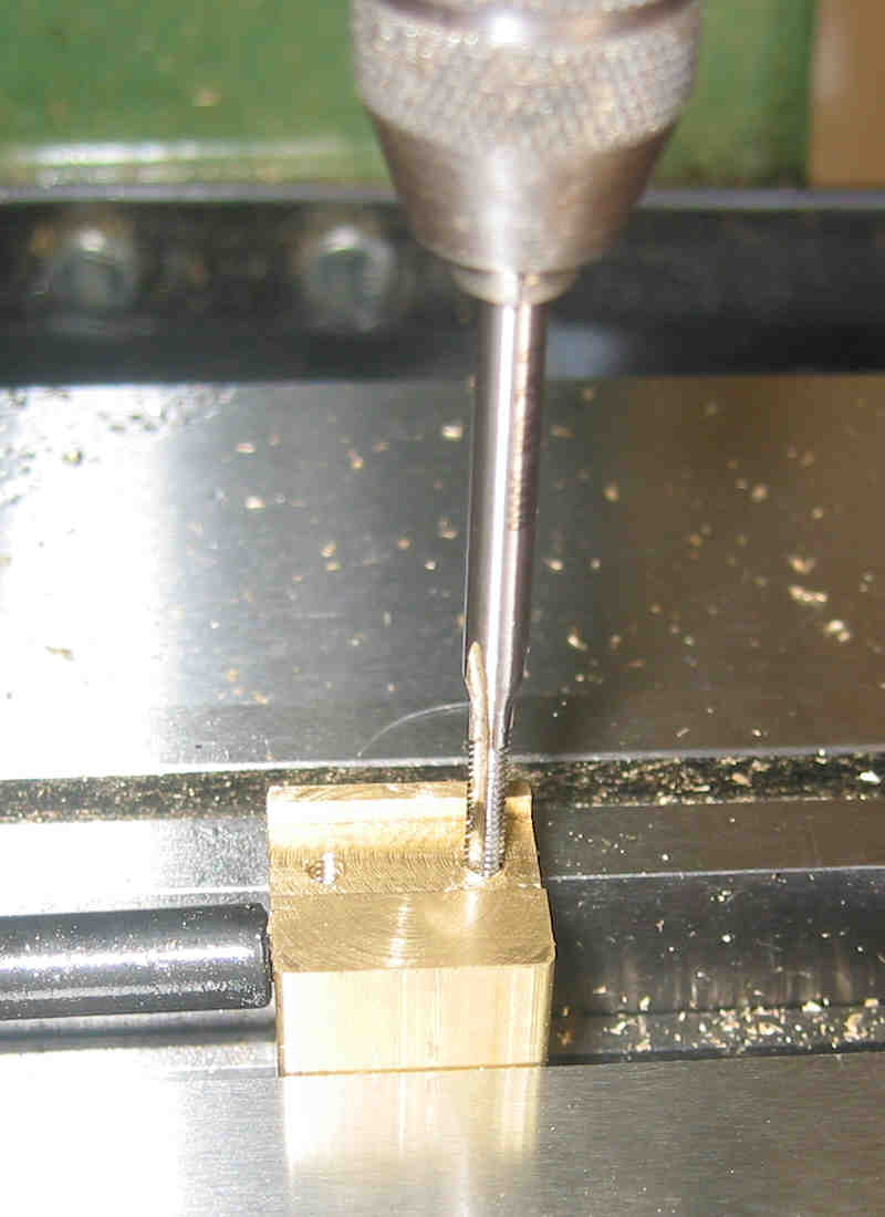
The picture on the right shows the boring operation on the last of the J-Boxes. The center drill and a 3/8" drill was used to get things started. The hole location was simply found by using a electronic edge finder in the x - y plane, move table to that point now zero them (although not shown, I did a use a stop in the x direction). Lock down the table and we are good to go! The hole diameter spec is very tight at .3940" to .3950", so we need a "go - no go" gauge (on the right). It has two diameters ... at the very end it's .3940" (the go), then the diameter changes to .3950" (no go). I lost a few J-Boxes because I wasn't careful enough in boring the bearing hole, the gage would "drop" in the hole .. diameter was about .397" plus in one case ... more scrapped parts!
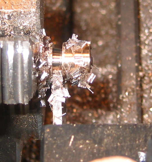
In boring ... you (I, that is) need to take into account flex and any change in the diameter setting is actually doubled! Go slow and take measurements after each cutting!!
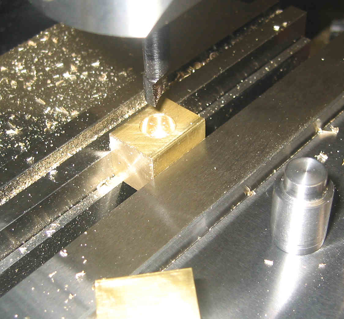
The "W" on the side ... it is actually a "3". I numbered each one and labeled the cutting side (the red line on top). It makes things a lot easier and quicker to know what side I need to cut before cutting!